Home Semiconductor Equipment Test Handler Test Handler Vibratory Bowl Feeder
Semiconductor Handler Infeed Integration

Test Handler Vibratory Bowl Feeder for IC Package Infeed

A test handler vibratory bowl feeder must do more than orient loose devices. It must present each IC at the correct height, direction and spacing, maintain a usable buffer, and exchange reliable ready, demand and fault signals with the handler.

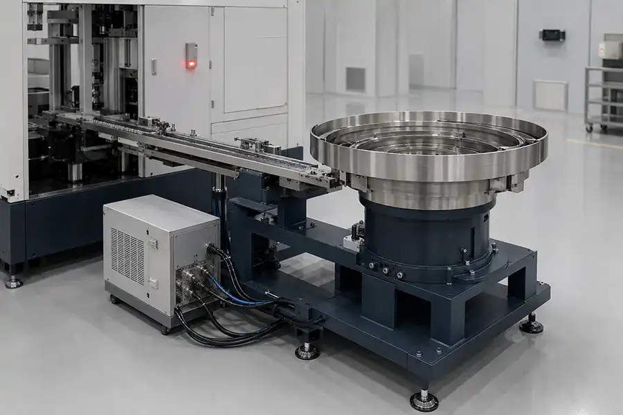
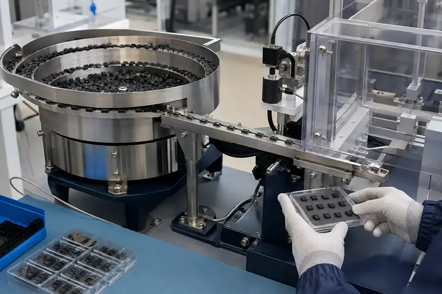
Test handler vibratory bowl feeder with controller and linear infeed track
Critical HandoffOne device, correct orientation, controlled spacing and a machine-ready signal
Device InputLoose packaged ICs
Feeder OutputOriented single-file flow
Handler InterfaceTrack, nest or pickup point
Control BasisDemand, buffer and fault status
Choose the Input Method First

When Does a Test Handler Need a Vibratory Bowl Feeder?

A bowl-input arrangement is most useful when singulated packaged devices arrive in bulk and the handler requires a continuous, consistently oriented stream. The input method should follow the device condition, lot handling practice and handler architecture.

A bowl feeder is a practical fit when

The device can tolerate controlled sliding contact and has features that allow mechanical orientation without touching critical terminals or functional surfaces.

Devices are supplied loose rather than in JEDEC trays, tubes or tape
The handler needs a replenishable single-file input buffer
Package geometry provides a dependable orientation reference
Lot loading and changeover procedures support bulk input

Another input method may be better when

Preserved pocket position, surface isolation, traceability by tray location or extremely limited device contact is more important than continuous bulk feeding.

Devices must remain in trays, tubes or carrier tape throughout handling
Exposed structures cannot accept track contact or recirculation
Multiple similar orientations cannot be separated consistently
The existing handler accepts only a proprietary carrier interface
Follow Every Transfer Point

Map the IC Package Path from Bowl Feeder to Test Site

Stable infeed depends on the complete device path. A good bowl result can still fail at the handler if the buffer, escapement or final handoff is not designed as part of the same sequence.

01

Bulk Load

Control lot loading, fill level and replenishment without overloading the bowl.

02

Orient

Reject incorrect attitudes and allow only the required device face and direction to pass.

03

Buffer

Maintain enough single-file accumulation to decouple bowl motion from the handler cycle.

04

Singulate

Separate one device at a time with controlled pitch and no trailing-device interference.

05

Handoff

Present the package at the specified track, nest, shuttle or pickup location.

06

Test Cycle

Release the next device only after the handler confirms capacity to accept it.

Integration rule: define ownership at the final handoff. The feeder and handler teams should agree who supplies the last track section, escapement, sensor, mounting plate, cable and control sequence.
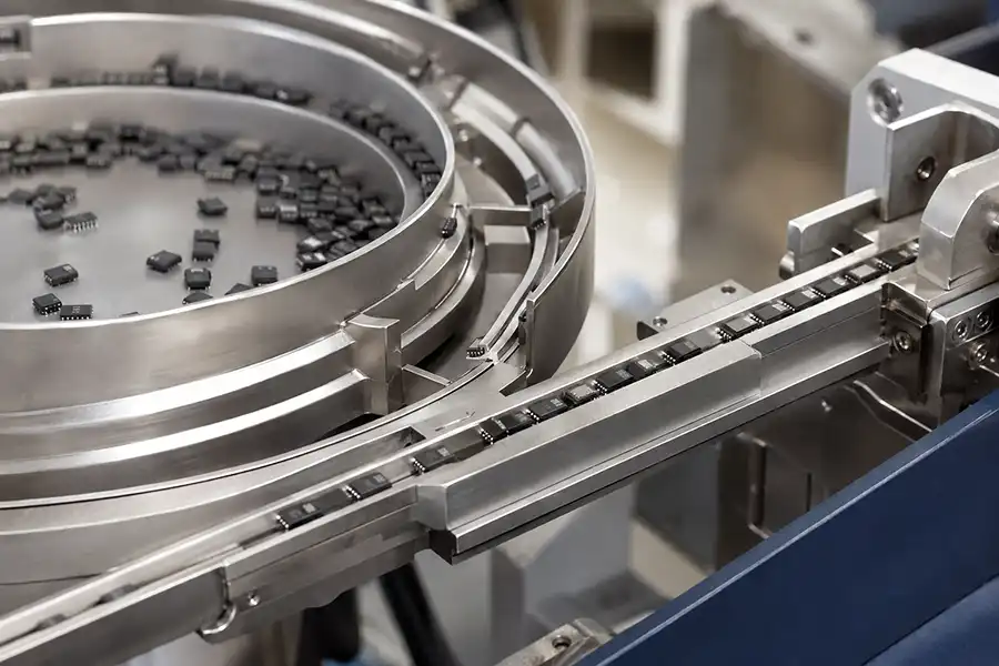
Precision bowl feeder tooling used to orient packaged semiconductor devices
Tooling follows the real packageOrientation features should be evaluated with representative devices, including normal dimensional and surface variation.
Device Handling Review

Which IC Packages Are Suitable for Bowl Feeder Infeed?

Suitability is decided by more than package name. Dimensions, mass distribution, lead or terminal exposure, marking direction, surface finish and the acceptable contact zones all influence the feeding approach.

01

Body Geometry

Length, width, height, chamfers and center of gravity determine how the package travels and separates.

02

Terminal Protection

Lead tips, pads, balls and exposed contacts should not become uncontrolled guide or impact surfaces.

03

Orientation Feature

Pin-one marks, asymmetric edges or body details must support a repeatable mechanical or vision check.

04

Surface & ESD

Track materials, coatings, grounding and cleaning methods should match the device handling requirement.

Packages often evaluated: QFN, DFN, SOT, SOP, LEDs, sensors, transistors and other singulated semiconductor devices. Final compatibility and feed behavior should be confirmed using actual samples and an agreed outlet condition.
Design the Handoff Before the Bowl

Interface Requirements Between a Bowl Feeder and Test Handler

The most important drawing is often the shared interface, where mechanical position, device condition and control responsibility meet.

MECHANICAL

Outlet Geometry

Fix the final device position relative to the handler datum before track tooling is released.

  • Track height and centerline
  • Discharge angle and direction
  • Mounting footprint and adjustment
  • Last-device retention method
DEVICE CONDITION

Presentation State

Define exactly what the handler must receive, not only what leaves the circular bowl track.

  • Top/bottom face and pin-one direction
  • Single-device pitch at release
  • Permitted contact surfaces
  • Minimum usable buffer quantity
ELECTRICAL

Machine Handshake

Agree voltage levels, signal direction, connector details and safe behavior when a signal is lost.

  • Handler demand or ready input
  • Device available output
  • Low level, jam and fault status
  • Reset, stop and interlock logic
Feed Only When the Handler Needs It

Control and Sensor Logic for Stable Test Handler Infeed

The bowl, linear track and escapement should respond to buffer condition and handler demand instead of running continuously at one fixed output.

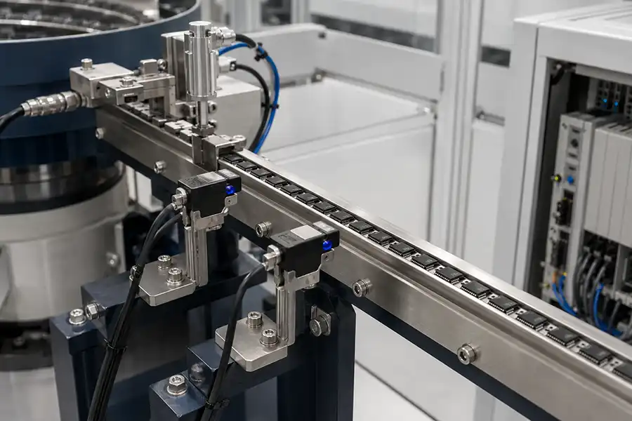
Semiconductor bowl feeder linear track with sensors and device escapement

A practical infeed state sequence

The exact I/O list depends on the handler, but the operating intent should be understandable at the interface review.

01
Call for devicesThe handler or buffer sensor requests replenishment when available device quantity falls below the defined level.
02
Build a controlled bufferThe bowl and linear drive run only as required; a full-buffer sensor stops further accumulation.
03
Confirm release positionA device-present sensor verifies that one correctly placed package is ready for the handler.
04
Release and acknowledgeThe escapement cycles after machine permission, then confirms completion or waits for pickup clearance.
05
Stop safely on abnormal stateTimeout, jam, guard or emergency conditions inhibit further release and provide a diagnosable status.
Match the Handler Motion

Bowl Feeder Integration by Test Handler Architecture

Different handlers consume devices differently. The last transfer should be shaped around the handler's motion, not forced into a universal outlet design.

Turret-Based

Indexing Pickup Position

The feeder presents one package at a fixed nest or pickup point. Pitch control, device stability and clearance for the turret tool are central.

Review: nest datum, pickup height and index timing
Gravity / Track

Controlled Track Entry

The oriented device joins a handler track or shuttle. Track cross-section, slope, gating and back pressure must remain compatible through the joint.

Review: rail profile, slope and release gate
Pick-and-Place

Defined Presentation Nest

The feeder builds a buffer and singulates into a nest where a robot or gantry can pick without adjacent-device interference.

Review: nest occupancy sensing and pickup access
Existing Machine Integration

How to Retrofit a Bowl Feeder to an Existing Test Handler

A retrofit starts with the handler as installed. Record the real datum, clearances, connector and operating sequence before choosing the new feeder footprint.

01

Capture the current interface

Provide handler model, inlet photos, dimensional drawings, mounting details, track height and nearby access restrictions.

02

Document the present cycle

Show how a device is requested, detected, released and cleared, including normal stop and fault recovery.

03

Confirm the shared supply boundary

Assign the adapter track, mounting stand, escapement, sensors, cables, connector and software changes.

04

Test the representative handoff

Evaluate actual devices through the final outlet condition and record observations against agreed criteria.

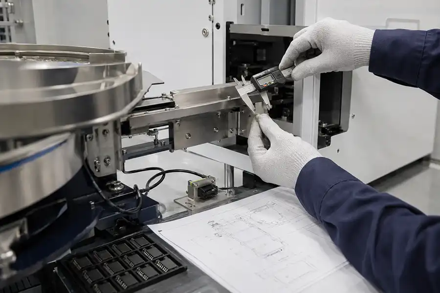
Test handler inlet measurement and semiconductor device sample review for bowl feeder retrofit
Measure from a shared machine datumPhotos are useful for context, but a retrofit outlet should be built from verified interface dimensions and connector information.
Diagnose the Location, Not Only the Symptom

Common Test Handler Infeed Problems and Corrective Actions

A stoppage observed at the handler inlet may begin earlier in the device path. Separate orientation, accumulation, singulation and handshake faults before changing vibration settings.

Representative IC package testing through a vibratory bowl feeder outlet
Observe the Full Path

Record where the device state first changes

Useful troubleshooting evidence connects the device position, sensor state, handler demand and feeder response at the same point in the cycle.

Observed ConditionCheck FirstPossible Engineering DirectionEvidence to Record
Handler starves intermittentlyBuffer sensor location, bowl recovery time and downstream demand patternResize usable buffer, revise demand thresholds or remove transfer restrictionsBuffer level and handler state immediately before starvation
Devices jam at the jointRail alignment, step, gap, track width and centerline between two suppliersCorrect the adapter profile and establish one controlled interface datumClose-up photos, device position and measured joint geometry
Two devices reach releaseEscapement pocket length, trailing-device restraint and sensor fieldRevise singulation geometry or release timingSlow-motion cycle at the escapement
Wrong orientation passesDevice variation, tooling wear, marking visibility and reject pathAdjust mechanical selection or add a suitable verification stepIncorrect device attitude and lot/sample reference
False device-present signalSensor technology, background, reflective surface and mounting vibrationChange sensing angle, threshold, shielding or device confirmation logicSensor state with empty, correct and abnormal positions
Feeder does not respond to demandI/O voltage, signal polarity, connector pins, interlocks and timeout stateAlign the handshake table and safe-state definitionHandler and feeder I/O states at the same timestamp
Prepare a Useful Technical Request

Information Needed for a Test Handler Feeder Project

The fastest way to clarify a handler infeed is to provide both device data and the machine interface. A feeder drawing without handler information leaves the most important transfer undefined.

Test handler infeed data checklist

Share the available items. Missing details can then be identified during the technical review.

Handler manufacturer and model
New installation or retrofit
IC package drawing and tolerances
Representative physical samples
Required face and pin-one direction
Expected input demand or cycle profile
Handler inlet drawing and track height
Pickup, nest or escapement details
Available installation envelope
Power, I/O voltage and connector list
ESD and permitted contact requirements
Sample-test and acceptance expectations
Technical Questions

Test Handler Vibratory Bowl Feeder FAQs

What does a vibratory bowl feeder do in a test handler cell?

It converts loose packaged devices into a controlled, single-file flow and presents them in the orientation, position and spacing required by the handler inlet. A complete infeed may also include a linear buffer, sensors and an escapement or presentation nest.

Which semiconductor packages can use bowl feeder input?

QFN, DFN, SOT, SOP, LEDs, sensors, transistors and other singulated packages may be evaluated. Suitability depends on actual geometry, exposed terminals, surfaces, weight, orientation features and acceptable device contact.

Can a bowl feeder handle delicate IC packages?

Track geometry, contact zones, coatings, vibration settings, grounding and recirculation paths can be selected to reduce handling risk. Final suitability should be confirmed with representative samples and clearly defined inspection criteria.

How does the feeder connect to an existing test handler?

The retrofit normally uses a verified mechanical datum, adapter track or presentation nest, mounting structure, sensors and an electrical handshake. The exact supply boundary should identify which party owns each interface item.

What outlet information is needed before feeder design?

Provide the required device face and direction, track centerline and height, discharge angle, pitch, pickup or gate position, permitted contact areas, buffer requirement and the relevant handler inlet drawing.

How are double feeds and wrong orientation prevented?

Mechanical selection features remove incorrect attitudes, while a correctly sized escapement restrains the following device during release. Depending on the application, sensors or vision may verify presence or orientation before handoff.

What signals are commonly exchanged with the handler?

Typical functions include handler demand or ready, device available, buffer full, low material, cycle complete, jam, fault, reset and interlock. Voltage, polarity, connector pins, timing and safe states must be agreed for the actual machines.

What should be provided for a test handler feeder quotation?

Provide the handler model, package drawing, samples, required orientation, expected demand, interface dimensions, available space, I/O details, ESD requirements and the desired test or acceptance conditions.