01
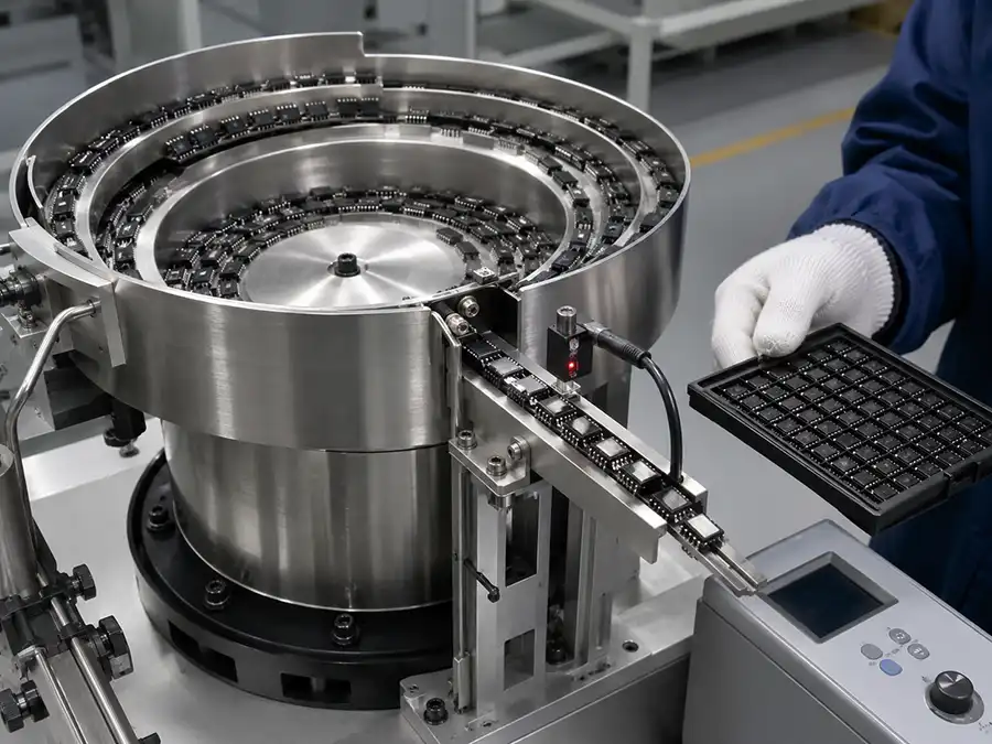
Feeder Bowl
Stores bulk parts and provides the spiral path used for separation and preliminary presentation.
GEEKVALUE-SEMI supplies application-based vibratory bowl feeder systems for randomly loaded parts that must be separated, oriented and delivered in a controlled sequence. Each project begins with the actual component, required outlet position, target rate and machine interface—not with bowl diameter alone.
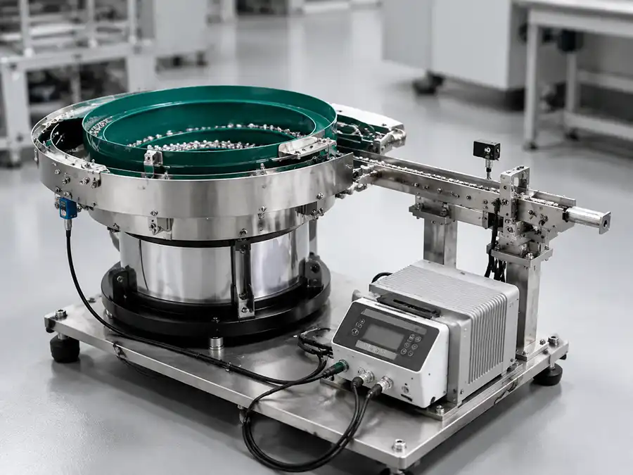
A vibratory bowl feeder is an automated parts-feeding system that uses controlled vibration and application-specific track tooling to separate, orient and present components one by one. Incorrect positions are returned to the bowl or rejected, while accepted parts continue through a linear track, buffer or escapement toward the next production process.
The bowl generates part movement, but reliable production also depends on orientation tooling, the drive, controller, accumulation control and the transfer into the next machine.
Two feeders with the same bowl diameter may perform very differently when their parts, required orientations, feed rates or downstream interfaces are different.
The required scope depends on how parts arrive, how they must leave and how the downstream equipment requests material.
Stores bulk parts and provides the spiral path used for separation and preliminary presentation.
Generates controlled vibration matched to the bowl mass, component behavior and required movement.
Uses rails, wipers, selectors, restrictions or air jets to retain acceptable positions.
Adjusts vibration frequency and amplitude to stabilize movement for the approved component.
Transfers oriented parts and maintains the queue needed by the machine input.
Monitor accumulation and support controlled single-part separation or machine-ready release.
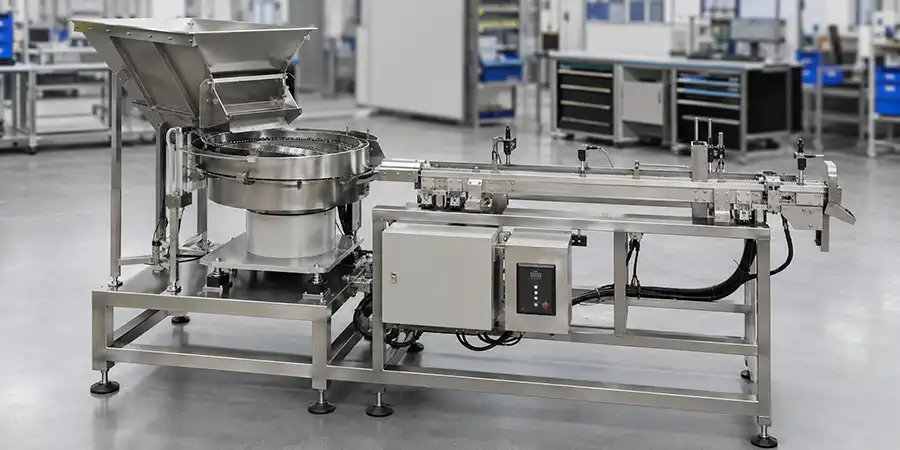
A stable design connects physical part behavior to the required production handoff.
Review geometry, weight, center of gravity, surface, fragility and possible stable positions.
Mark the exact outlet position and identify features that can confirm or reject it.
Match track direction, height, buffer, separation method and downstream inlet.
Observe output, wrong positions, jams, doubles and part condition against agreed criteria.
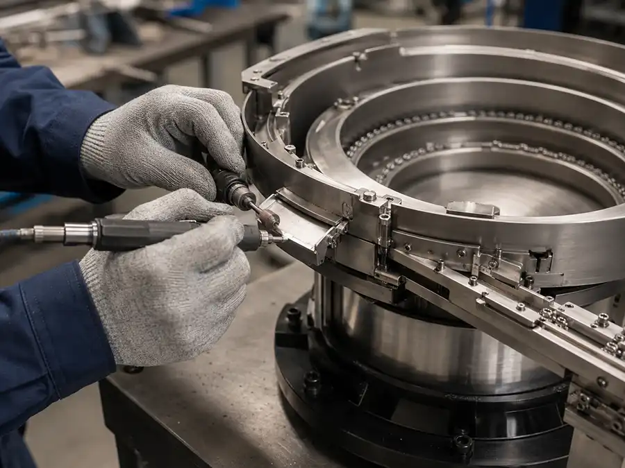
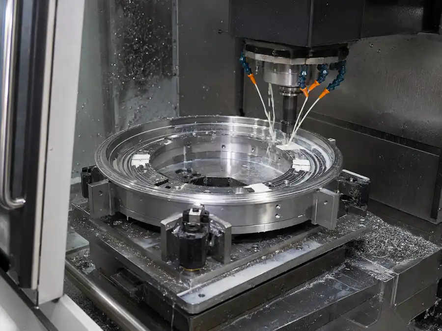
Feeder configuration depends on the component, required orientation, production rate and downstream process.
Present compatible packaged devices to a handler track, pickup point or indexing mechanism with controlled accumulation.
Supply oriented components for identification, inspection, electrical testing, grading or binning.
Maintain a known component face, direction and spacing before camera-based inspection or measurement.
Feed accepted parts toward counting, pocket loading, tube loading or other packaging operations.
Orient suitable electronic components while considering small feature differences and appearance-sensitive surfaces.
Deliver mechanical or electronic parts in a repeatable pose for insertion, fastening, robotic pickup or assembly.

Drawings establish dimensions and tolerances, but they do not fully show friction, center of gravity, nesting, tangling, surface sensitivity or how several parts interact under vibration.
Representative samples are especially important for small electronic parts, components with several stable positions and parts whose appearance or leads can be damaged by uncontrolled contact.
An accurate quotation requires the component specification, output orientation, target rate and machine interface. These details determine the tooling concept, control scope and integration requirements.
| Requirement | Engineering Question | Project Information |
|---|---|---|
| Part geometry | Which physical features can establish orientation? | Dimensioned drawing, 3D model, photographs and tolerances. |
| Material and surface | Can the part slide and contact other parts without damage? | Material, finish, fragile areas, cleanliness and allowable contact. |
| Required orientation | Which face and direction must reach the machine? | Marked outlet-orientation drawing or photograph. |
| Target output | What continuous rate and buffer are actually required? | Parts per minute, UPH, machine cycle and demand pattern. |
| Machine interface | How will the part leave the feeder and enter the process? | Inlet height, direction, track profile, installation space and drawing. |
| Controls | How does the feeder respond to demand and accumulation? | Voltage, sensors, start-stop logic and PLC or machine signals. |
| Environment | Are ESD, particles, noise or material restrictions relevant? | Production-area requirements and any measurable acceptance limits. |
| Sample test | How will the proposed system be verified? | Representative parts, test quantity, duration and acceptance criteria. |
A bowl feeder is valuable when its mechanical orientation advantages match the production mix and component risk.
Often suitable for high-volume feeding of a consistent part with mechanically detectable orientation. Custom tooling is normally component-specific.
Can suit mixed production or parts whose correct pose is more practical to identify visually, although robot, camera and cycle requirements must be evaluated.
May be preferable for bare dies, fragile surfaces, contamination-sensitive devices or components already supplied in a controlled orientation.
When selecting a manufacturer, confirm the proposed orientation method, complete supply scope, sample-testing procedure, interface responsibility and acceptance criteria. Price comparisons are meaningful only when the quoted system boundaries are equivalent.
The test record can document the approved sample lot, outlet orientation, observed feeding rate, incorrect-part rejection, jams, part condition and interface response.
Price depends on the part, orientation complexity, tooling, required rate, included modules and integration boundary. A detailed RFQ produces a more meaningful technical and commercial comparison.
It separates randomly loaded parts, establishes a repeatable orientation and delivers them in a controlled sequence to downstream testing, sorting, inspection, packaging or assembly equipment.
A controlled drive moves parts along a spiral track. Application-specific tooling retains correct positions and returns or rejects incorrect ones before accepted parts enter a track, buffer or escapement.
Compatible packaged ICs, LEDs, SMD parts and other electronic components can be evaluated. Suitability depends on geometry, surface sensitivity, required orientation, output and downstream interface.
Not automatically. Bare dies and fragile surfaces may be vulnerable to contact, particles, impact or electrostatic risk. Tray, tape, tube or another protected presentation method may be more appropriate after engineering review.
Price depends on part behavior, bowl and drive size, orientation tooling, coating, required output, controller, hopper, linear track, sensors, escapement and machine-integration scope.
Compare application analysis, proposed orientation logic, included modules, representative sample testing, interface responsibility, documented acceptance criteria, warranty and support boundary.
Use production-representative parts from the expected dimensional and surface range. The manufacturer should confirm the required quantity and whether different batches or known variants must be included.
It may be possible after confirming the handler inlet, required package orientation, track height, available space, buffer, sensors, voltage and control signals.
Send drawings, part photographs, representative samples, required output position, target feed rate and downstream equipment information for an application review.