Feeding Concept
Defines the accepted outlet position, orientation logic, rejection approach, buffer requirement and downstream release condition.
GEEKVALUE-SEMI designs and builds custom vibratory bowl feeder systems for packaged ICs, SMD and LED components, metal parts, plastic parts and other precision automation applications.
Each feeding system is engineered around the actual component, required discharge orientation, target feed rate and downstream machine interface. Bowl tooling, linear tracks, sensors, escapements and control requirements are developed as one coordinated system and verified with representative samples before shipment.
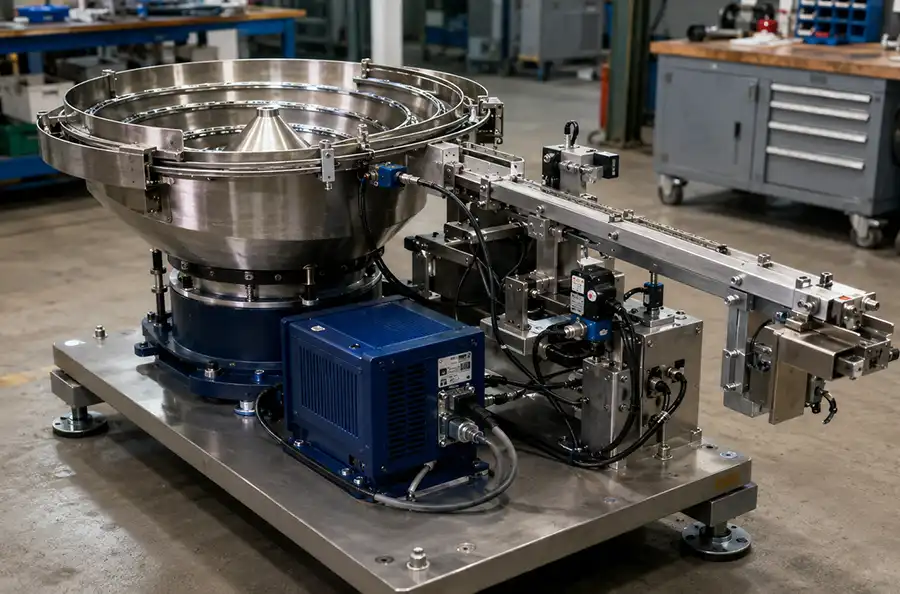
The useful deliverable is an application-specific feeding result, not an isolated polished bowl or a catalogue drive unit.
Defines the accepted outlet position, orientation logic, rejection approach, buffer requirement and downstream release condition.
Identifies the bowl, drive, tooling, controller, base, track, sensors, escapement and any optional loading or enclosure modules.
Connects the approved sample lot and test conditions to observed orientation, output, jams, doubles and component condition.
Clarifies dimensions, discharge height, track profile, signals, utilities, installation space and the handoff to customer equipment.
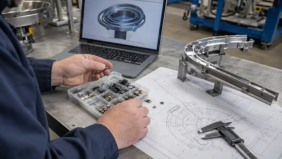
A staged approval path reduces late changes and makes the technical and commercial boundary visible before shipment.
Collect drawings, samples, variants, orientation, target rate, machine details, environment and destination requirements.
Identify stable positions, difficult features, surface risks, nesting behavior and the information that still requires confirmation.
Agree on supplied modules, outlet geometry, controls, responsibility boundary, sample lot and acceptance method.
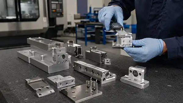
Build the bowl tooling, machined interface parts, support structure and controls around the approved project basis.
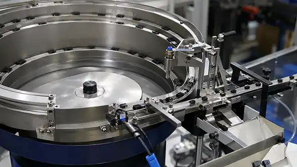
Run representative parts, observe failure modes and tune the feeding path within the agreed verification conditions.
Release the approved configuration, test record and applicable interface information for installation or line integration.
Compare the proposed project basis and verification plan—not only the bowl diameter, headline rate or total quotation value.
| Review Area | What the Manufacturer Should Define | Useful Project Evidence | Warning Sign |
|---|---|---|---|
| Application analysis | Part behavior, possible orientations and major feeding risks. | Questions tied to the drawing and physical samples. | A quotation based only on bowl size and speed. |
| Orientation concept | Required discharge pose and how incorrect positions are returned or rejected. | Marked outlet drawing, concept explanation or sample review. | No defined outlet position before build. |
| Supply scope | Included mechanical, electrical, control and support modules. | Itemized scope with optional and excluded items identified. | “Complete system” without a module list. |
| Machine interface | Discharge height, direction, track profile, mounting, utilities and signals. | Interface drawing or responsibility matrix. | Integration deferred until after shipment. |
| Sample verification | Parts, variants, test duration and observations used for approval. | Test plan, video or record connected to agreed criteria. | Unqualified claims such as “high accuracy.” |
| Change control | How part revisions, new variants or interface changes affect the project. | Design-freeze point and written revision process. | Changes accepted verbally with no scope impact review. |
| Handover support | Documents, setup information, spare recommendations and support boundary. | Defined handover package in the quotation. | No named responsibility after delivery. |
A lower quotation may exclude the hopper, linear track, sensors, escapement, support base, controls or integration work.
Output and orientation statements are meaningful only when the approved parts, test conditions and measurement method are known.
Mechanical handoff, utilities, sensors, PLC signals and installation fit must have a clearly named owner.
Two quotations can describe very different projects even when both use the phrase “complete vibratory bowl feeder system.”
A useful factory acceptance test records the conditions and observations behind the approval instead of relying on a short unreferenced demonstration.
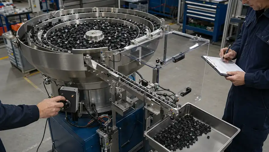
The FAT should state what was tested, how it was observed and which items remain dependent on final line integration.
Custom feeder price and project duration are driven by engineering uncertainty, tooling complexity, supplied modules and verification requirements—not by one universal price list.
Small orientation features, several stable positions, tangling, nesting and surface sensitivity increase engineering and tuning effort.
One fixed component is different from a family of parts requiring common tooling, controlled changeover or replaceable tracks.
Higher sustained rates, multi-lane discharge and low-buffer applications can change bowl, track and escapement requirements.
Hoppers, linear feeders, sensors, escapements, sound enclosures, bases and controls expand the delivered system boundary.
Custom discharge geometry, restricted installation space, interface fabrication and line-level communication add coordination work.
Multiple variants, long-duration testing, measurement equipment and customer-witnessed approval affect preparation and scheduling.
Include expected batches, tolerances, surface conditions and known variants instead of sending only ideal parts.
Use a marked drawing or photograph that shows face, direction, spacing and the reference point at discharge.
Define whether the rate is peak, continuous, buffered or measured with the real downstream demand pattern.
Freeze the inlet geometry, height, direction, support points, utilities and signal boundary before fabrication.
Identify sensitive surfaces, leads and cosmetic limits before testing, then inspect parts after repeated feeding.
Normalize included modules, drawings, FAT, packing, installation and support before comparing total price.
A detailed initial package allows manufacturers to assess feasibility, identify exclusions and compare the same project boundary.
The quotation should identify the approved application basis, supplied modules, outlet condition, controls, sample requirements, verification method, documentation, packing, delivery boundary and excluded integration work.
Drawings do not fully show friction, nesting, tangling, center of gravity, surface sensitivity or how parts interact under vibration. Representative samples allow these behaviors to be evaluated before final tooling and acceptance.
A preliminary concept may be possible, but final feasibility, tooling and performance commitments can depend on testing representative parts. The quotation should clearly state any assumptions that remain unverified.
The rate should be connected to a defined sample, outlet orientation, observation interval and downstream demand condition. Peak movement in the bowl is not the same as sustained machine-ready output.
Factory acceptance verifies the agreed functions available at the manufacturer's facility. Site acceptance can additionally verify installation, utilities, safety circuits, line controls and interaction with the real downstream machine.
Sometimes, but the variants must be reviewed together. Differences in dimensions, center of gravity, surface, orientation features or tolerances may require adjustments, change parts or separate tooling.
Tooling complexity, part variants, required output, included modules, interface work, controls, enclosure, documentation and the verification plan can all change the project cost.
Normalize the supplied modules, sample assumptions, outlet requirement, performance definition, integration boundary, acceptance plan, documentation and support scope before comparing total price.
Send the drawing, representative samples, required outlet position, production demand and machine interface. We will review the custom feeder project basis and the information needed for a meaningful quotation.