Load
Loose IC packages enter the bowl in a controlled quantity.
Sort loose IC packages into one direction and deliver them in a controlled line to testing, inspection, sorting or tape-and-reel equipment. Each feeding system is matched to the actual package, required orientation and receiving machine.
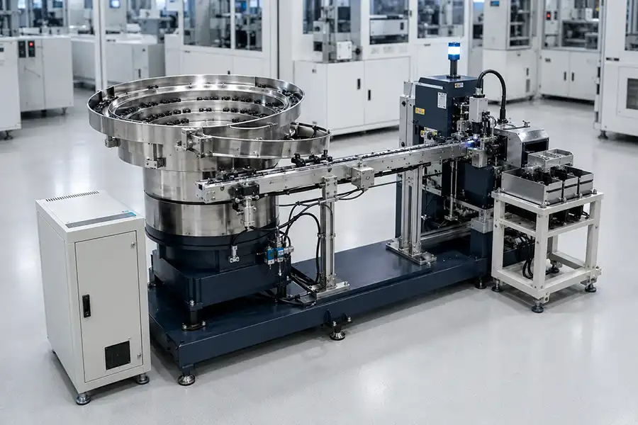
An IC vibratory bowl feeder is an automatic feeding system that takes loose packaged semiconductors, turns them into the required direction and moves them in a single line to another machine. It commonly supplies test handlers, inspection machines, IC sorting systems and tape-and-reel equipment.
Controlled vibration moves the packages around a shaped track. Guide features remove packages in the wrong position, while correctly oriented packages continue to the outlet.
Loose IC packages enter the bowl in a controlled quantity.
Gentle vibration advances the packages around the internal track.
Track guides keep the required position and return incorrect positions.
Correct packages enter the straight track in one controlled line.
The outlet presents each device to the next machine at the agreed position.
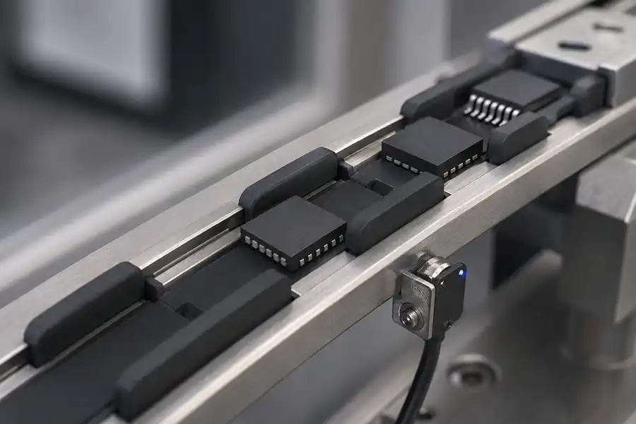
Small packages can have exposed leads, pads, balls, markings or sensitive top surfaces. Protection starts by identifying where the device may safely touch the bowl and track.
Guide the body on approved surfaces and provide clearance around leads, pads or balls.
Set the movement high enough for stable travel without unnecessary impact or jumping.
Select a finish or coating that supports smooth movement and limits marking or sticking.
Use grounding and suitable materials when electrostatic discharge, or ESD, control is required.
Many individual semiconductor packages can be evaluated, but package family names do not guarantee the same feeding result. Body dimensions, terminal shape, weight, surface condition and required direction must be checked.
| Package Group | Typical Feeding Need | Main Point to Check | Possible Outlet |
|---|---|---|---|
| QFN and DFN packages | Face and pin-one direction with controlled spacing | Bottom pads, small height and top/bottom similarity | Linear track, pickup nest or handler inlet |
| SOT and transistor packages | Body direction and lead-safe movement | Lead clearance and uneven weight distribution | Guide track or test machine input |
| SOP and small leaded ICs | Consistent body direction without bending leads | Lead span, body width and rail support | Linear buffer or transfer nest |
| LED and sensor packages | Surface-aware orientation before inspection or test | Lens, window, marking and sensitive top surface | Inspection, sorting or taping machine |
| Other discrete packages | Single-file output in a repeatable position | Body shape, terminals and available orientation feature | Custom track or machine-specific handoff |
The required output should be described as a visible package position: which face is up, which end leads and where pin one must point. This is clearer than using only clockwise or counterclockwise.
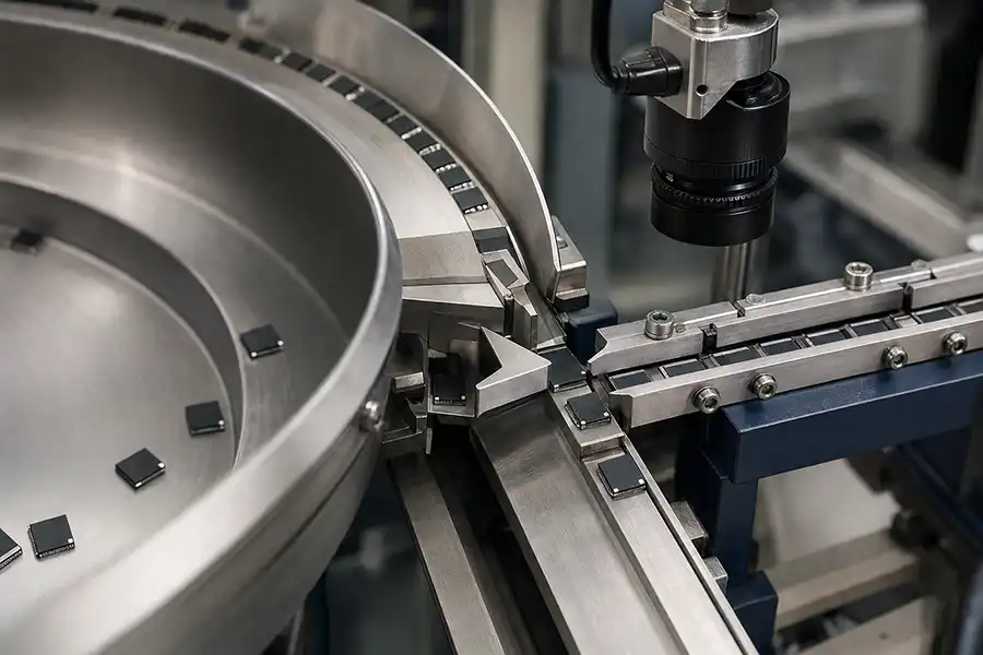
Each check answers one simple question about the device when it reaches the feeder outlet.
The feeder outlet is prepared for the next process. The same package may need a different final track or release method depending on how that machine accepts the device.
Supply oriented packages to a handler track, shuttle, nest or pickup position. For detailed handler integration, review our test handler vibratory bowl feeder page.
Present the same face and direction so cameras can inspect markings, package surfaces, leads or other visible features.
Provide a controlled stream before identification, measurement, testing, counting or separation into different output groups.
Deliver devices in the direction required for pocket loading, inspection and sealing into carrier tape.
Sometimes, but only when the packages have compatible dimensions, safe contact points and output requirements. A wide size difference or different terminal structure usually requires change parts or a separate feeder.
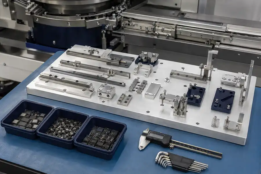
Start with the actual package and required outlet. Bowl diameter alone does not tell you whether the device can be oriented, protected and delivered to the next machine.
Provide length, width, height, weight, tolerances, photos and a drawing showing terminals and sensitive areas.
Show which face is up, which end leads, pin-one direction and the final stop or pickup position.
State the normal machine demand and short peak demand instead of only giving a maximum number.
Provide the machine model, inlet drawing, track height, available space and method used to accept one device.
Confirm how the feeder knows when to run, stop, report low material or indicate an abnormal condition.
Use real production samples to observe travel, orientation, condition and delivery at the agreed outlet.
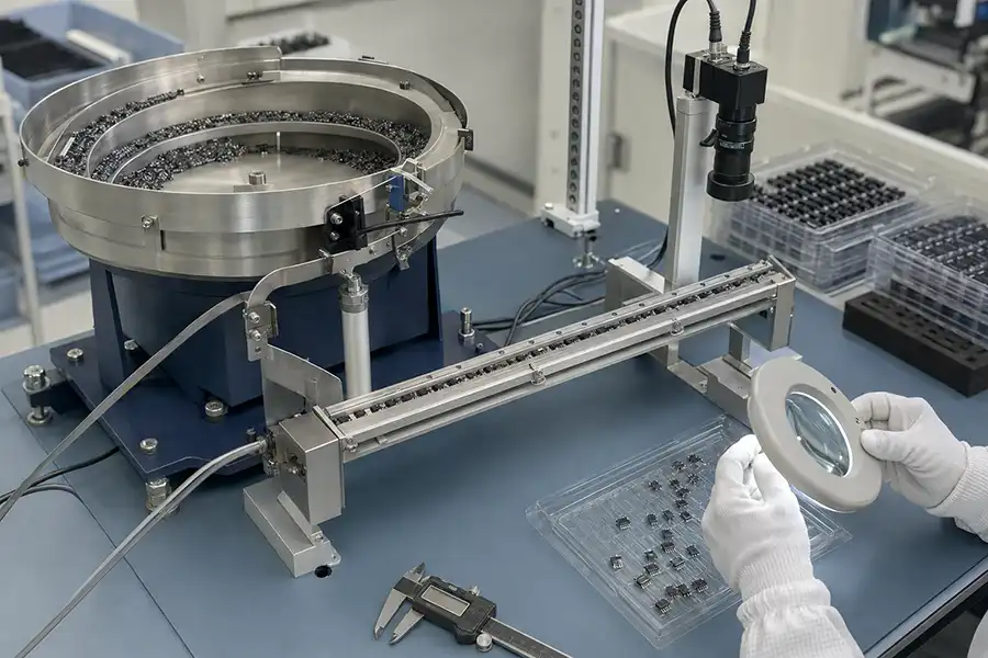
A useful sample test checks repeatable feeding and device condition under an agreed setup. One short video of a single package is not enough to describe the complete result.
Watch for stacking, turning, sticking, excessive jumping or trapping between parts.
Confirm face, leading end and pin-one direction at the feeder outlet.
Check spacing, release of one device and smooth transfer into the receiving point.
Inspect agreed areas for visible marking, bent leads, surface damage or unwanted material.
A drawing explains dimensions, while physical samples show how the molded body, terminals and surfaces behave in the track. Providing both gives a clearer basis for review.
Share the available items and clearly identify any details that are still being confirmed.
Use the related pages to review the complete feeding system, test handler connection and custom project supply process.
It takes loose packaged ICs, arranges them in the required direction and delivers them in a controlled line to testing, inspection, sorting or packaging equipment.
QFN, DFN, SOT, SOP, LEDs, sensors, transistors and other individual semiconductor packages may be evaluated. Final suitability depends on the actual dimensions, terminals, surfaces, weight and required output position.
The feeding path can be designed around safe contact areas, lead clearance, suitable track surfaces and controlled movement. Representative samples should still be tested and inspected against agreed package-condition requirements.
Custom guide and selection features use differences in body shape, edges, terminals or weight to return incorrect positions. When package geometry is not enough, an additional sensor or camera check may be considered.
Yes, when the package provides a dependable feature that can be used to separate or verify its direction. The required face, leading end and pin-one position should be clearly shown before design.
It may be possible for closely related packages using adjustable guides or change parts. Large differences in size, terminal layout or required output often make separate tooling or a separate feeder more practical.
Common receiving equipment includes test handlers, inspection machines, IC sorting systems, programming machines and tape-and-reel equipment. The final outlet must match the actual machine inlet.
Send the package drawing, photos, samples, required orientation, machine demand, receiving machine model, inlet dimensions, available space and any package-protection or static-control requirements.
Provide the drawing, representative samples, required output direction and receiving machine information so the complete device path can be reviewed around the real application.